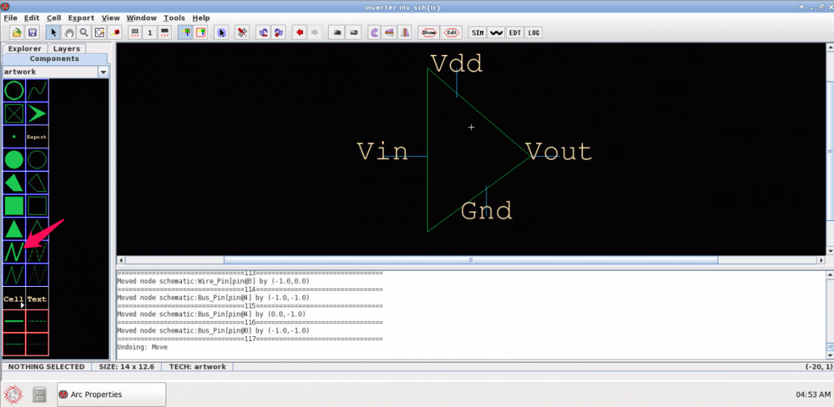
![[object Object]](https://umsousercontent.com/lib_CUsguFEVafmoKCKW/ns6hm1s6vu8ctynd.png?w=334)
Electric calls the symbol view an icon, and uses the “ic” abbreviation. You can auto-create a basic (rectangular) icon from a schematic that has exports defined, then edit the icon artwork. It is normal to show a cell’s icon view directly in its own schematic (at the above-right, an instance you are free to move or delete).
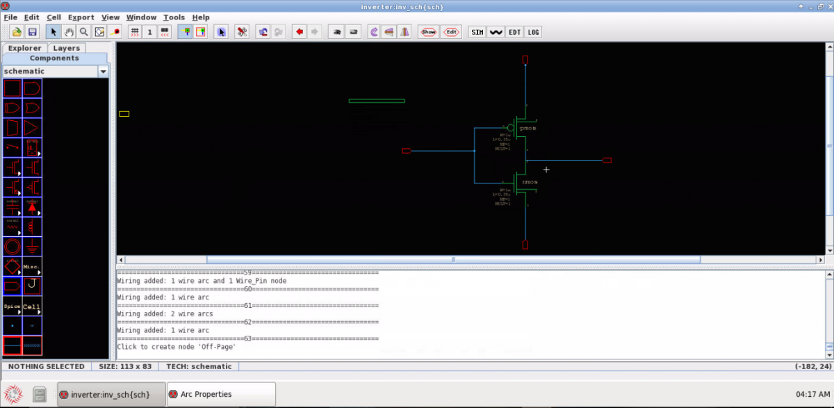
Consider the following inverter schematic that needs a symbol. Name the input, output and power supply wires: double-click a wire, edit the Name field and hit Ok on the form. Naming a wire triggers a label to appear centered on the wire; drag the name label anywhere you wish.

Add (select and place) nodes (Components ? schematic ? node) to the input, output and power supply wires. Rename the nodes to the same names as the wires (double-click the node to get a Properties form). Ensure all wires are connected. When your cursor is over a component in the side-bar, the status-bar will say: “CREATE NODE: …” with name of that node; here we’re using the node Off-Page. The Off-Page shape can change, once the node is associated with an export to reflect some export Characteristic values.
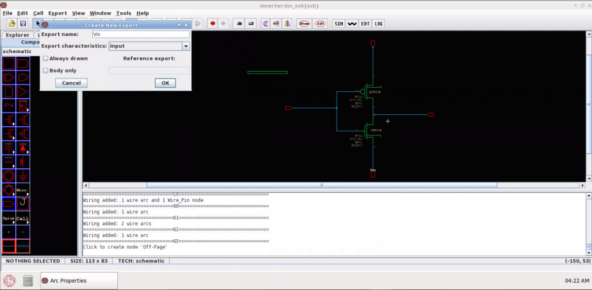
The first step in auto-making an icon is to expose the pins in the schematic. Export the I/O and power nodes: Select a node, then go to menu item Export–> Create new export. Enter the node name and assign a Characteristic from the drop down menu. As soon as you click OK, the connected wire is highlighted indicating the connectivity.
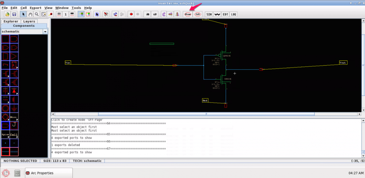
In the Toolbar, click the Show button to view all exported nodes. Exported nodes can be edited using Edit toolbar button.
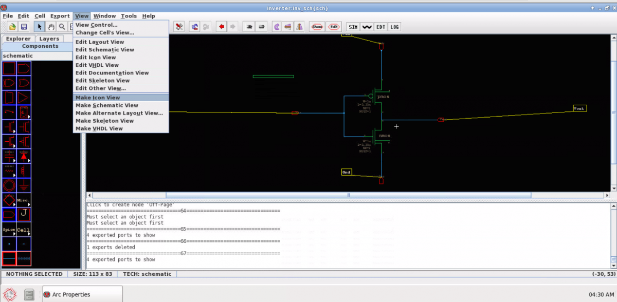
Menu item View ? Make Icon View creates the icon view which can be seen in the side-bar Explorer tab under the schematic
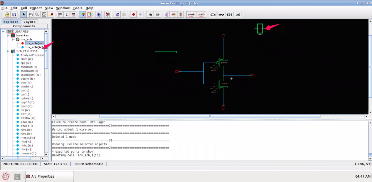
The auto-created icon view is also placed in the cell’s own schematic for easy reference. Note, in the Explorer if you try to delete an icon Electric refuses if it’s used (placed) in any cells (in any open library); and this counts its own schematic (simply delete the icon placement in the schematic as needed).
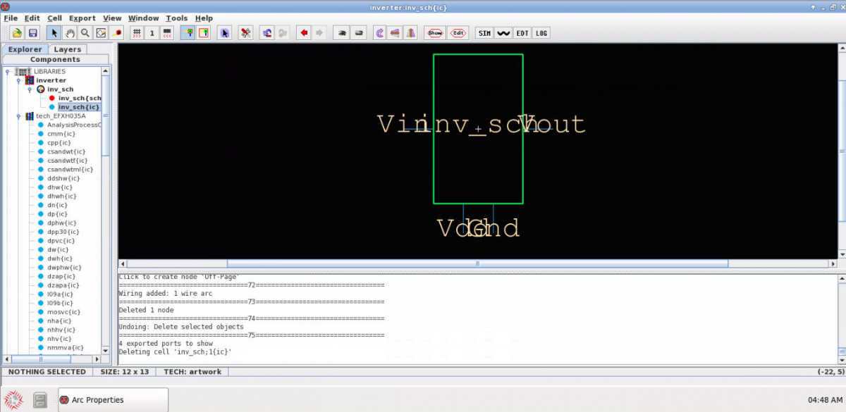
The box can be modified to any desired shape by using the options under artwork in the side-bar Components tab.
The icon is ready to be used in another schematic. Cell icons can be instantiated in a schematic by: dragging the icon view from the Explorer in the side-bar, or use menu item Cell ? Place Cell Instance, or the N key, or right-click on the icon in Explorer and select Place Instance of Cell.