![[object Object]](/lib_CUsguFEVafmoKCKW/ns6hm1s6vu8ctynd.png?w=334)
- In the projectManager, the “Pad Frame” button launches a tool by which to generate a pad-frame that you define via simple tables in a spreadsheet.
- The outputs are: electric symbol, magic layout, and post-layout extracted spice netlist.
Outline:
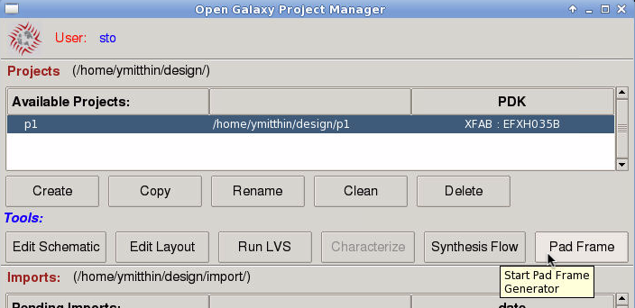
- Using the projectManager: create or select a project in the EFXH035B PDK, click “Pad Frame”.
- Answer prompts for the pad-frame cell’s: electric library-name and cell-name of the symbol and layout.
- Edit spreadsheet to define your pad-frame. If you previously created a spreadsheet for the same cell-name, it is reopened . The initial spreadsheet includes a sample pad-frame definition.
- Hit Generate button (will overwrite an existing symbol and layout). Generate runs magic and displays the layout.
- Verify at end of the magic console that no errors are reported and three result files were written: electric symbol, spice netlist view, magic layout. Save and exit the spreadsheet.
- View and place the symbol in your own schematic (using Electric). View and place the layout in your own layout (using magic).
Usage Tips:
- In the spreadsheet, only edit the PadFrameDesign sheet, and then only the column-pairs under South, East, North, West. These define the pad cells, each with a unique name, of each side (south, east, north, west) and what order they are in, going counter-clockwise starting from the left-end of the south edge.
- Don’t intersperse empty rows in these columns. The first empty Cell field terminates that side’s pad list.
- Fill cells can optionally be manually placed in these columns but the Name field adjacent to an explicit fill-cell must be empty. You can view available fill-cell names and widths in the Tech.PL sheet, such as: IOIBFILL7P.
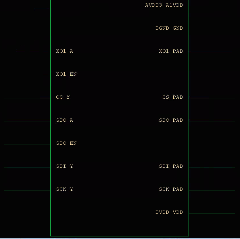
- In the output symbol, the south, east, north, and west IO ranges are simply vertically stacked in that order from the top of the symbol downward. The Name field in the spreadsheet and the IO-cell’s pin names are concatenated (with “_”) to name each pad-frame pin.
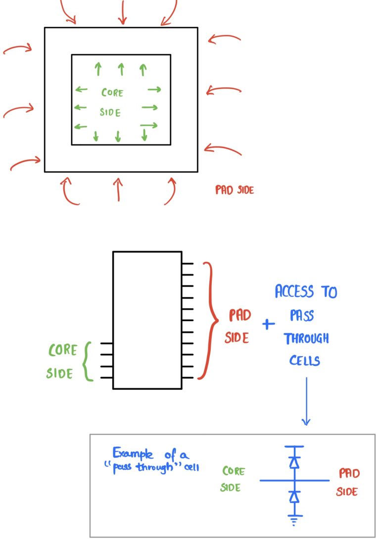
- Core-facing pins are placed on the left-side of the symbol, and off-chip pad pins on the right, aligned horizontally if relating to the same IO-cell. Be aware some IO-cell pads by design pass-thru to the core. In this case the symbol only shows the pad pin on the right-side, and when used in a schematic you will need to make connections from it to the core. Examples of this are the cell:pin pairs: VDDALLP:VDD, GNDALLP:GND, H_ANIMP:PAD, GNDAN1P:A1GND, VDDAN1P:A1VDD.
- Depending when your UNIX account was created, your libreOffice dot-files (~/.config/libreoffice/) may be old. If opening the padframe spreadsheet prompts you whether or not to Enable Macros, your libreOffice dot-files are old.
You may prefer to reset your libreOffice dot-files: exit any running libreOffice tools, and from a Terminal (shell) run the command: resetLibreOffice.
Limitations:
- Only works for EFXH035B PDK. The EFXH035A, EFXH035C PDKs do not have IO CELLS installed.
- Only works for pad-limited case; not core-limited.
- Does not work for IO-pad cells: axtoc01, axtoc02. They do not have one centered PAD, and widths are not multiples of the pad-frame grid.
Steps by example:
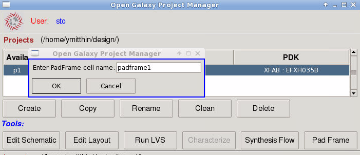
Starting Pad Frame generator from the projectManager, below with project “p1” selected (associated with EFXH035B PDK):
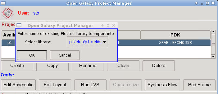
It prompts for Electric library-name and cell-name of symbol and layout. Below showing libary “p1.delib” selected, and entering cell-name “padframe1”. To keep your pad-frame in a new Electric library, create a new library within Electric before hand.
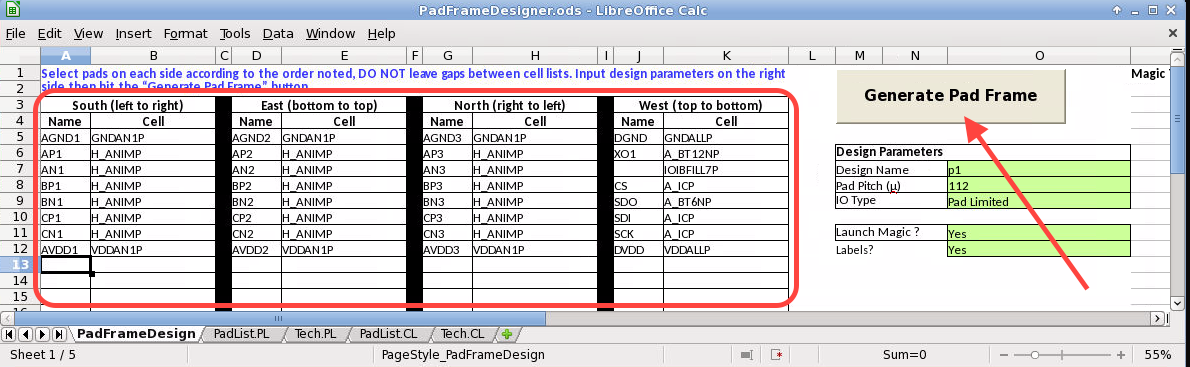
Edit the South, East, North, West column pairs (below encircled in red) to define your pad-frame, in the PadFrameDesign sheet. Keep the “Name” fields unique. Click the “Generate Pad Frame” button to run the generator (highlighted below with red arrow).
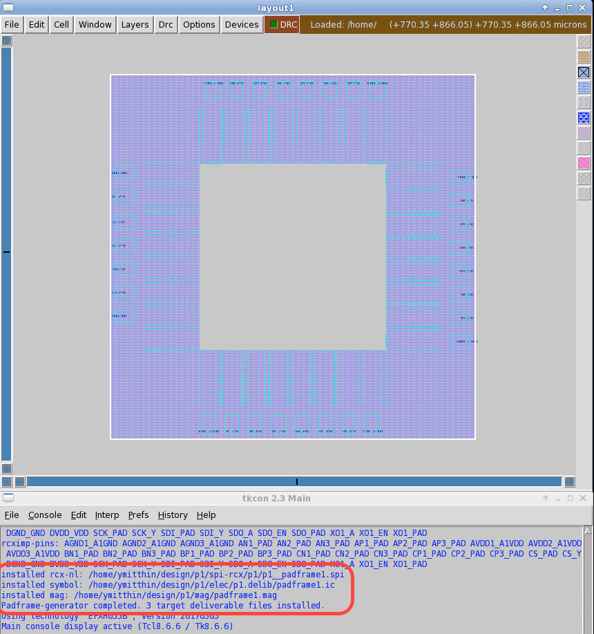
Example of the magic layout view that results (from default spreadsheet entries as above), with success messages encircled in red in the console.
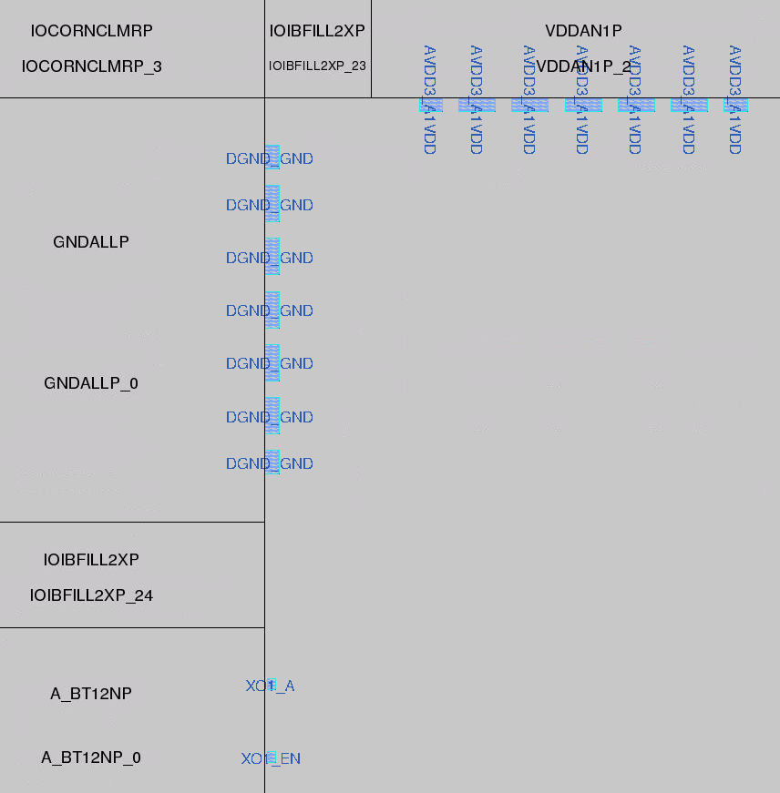
A part of the layout, inside upper-left corner, cell placements unexpanded, showing core-facing pins:
In projectManager, click “Edit Schematic” to start Electric, and in the Explorer open the “p1” library and double-click to view the “padframe1{ic}” symbol:
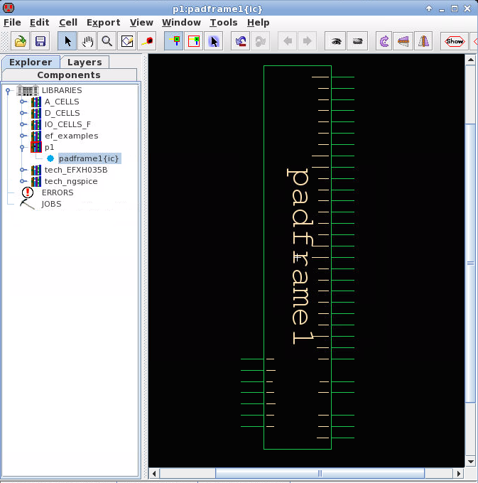
A part of the symbol showing side-by-side core-facing pins (on left) and off-chip PAD pins on right from the same IO-cells: